
|
|
Software - AutoGuider and Focuser Control Program (AGFP)
|
||||
|
AutoGuider and Focuser Control Program (AGFP) is used to communicate with the AutoGuider Focuser
Microprocessor unit (AGFM).
The AGFP program is written in Visual Basic .net framework and will run on any Microsoft Windows
based PC or any system that supports .net framework 4.0 or higher.
Download AutoGuider_Focuser_Control.zip
There are 2 hardware versions of the AGFM. One using a Basic Stamp 2 and the other using a Arduino nano. |
||||

Menu bar functions:
|
||||

Sending commands and functions:
This example shows the program connected to COM15 and doing a timed giude and focus for 10000ms (10 seconds). The North, East, 1 In and 2 Out buttons were pressed and the counters are updating every 500ms (0.5 seconds). The autoguider port moves the mount in the selected direction at the mount's current guide or slew rate depending on the mount as long as the button is pressed. If Timed Guide is checked the button click will move the mount for the number of milliseconds indicated or until the Stop button is pressed. Focus motor buttons work the same as the autoguide buttons except when the Timed Focus is less than 10000ms (10 seconds). For Timed Focus between 5ms and 9999ms focus commands are issued to allow the AGF controller to do the focus duration. The log box shows command communications to and from the AGF. |
||||

|
||||

|
||||

Keyboard control:
Click on 'Key' to enable the keyboard to send commands to the AGFM.
|
||||

About/Help:
About/Help window.
|
||||

Shrink/Restore window:
Will make the window narrow hiding some functions and displays.Shrink changes to Restore put the window back to normal width. Use 'S' key or Shrink menu command. |
||||

Disconnect:
Controller functions are disabled when not connected to a COM port.
|
||||

Exit:
Program Exit will display a save window to allow setting to be saved.
Ending the program with the Windows X at the top right of the main program window will save the settings without asking. |
||||
Hardware - AutoGuider Focuser Microprocessor unit (AGFM) using Basic Stamp 2 (1st Generation Box)
|
||||
|
AutoGuider Focuser Microprocessor unit (AGFM). The AGFM is a microprocessor based control box that uses the Parallax
Basic Stamp 2 to control a ST4 type AutoGuider port of any telescope mount. It also will control
2 focus motors using an internal 9VDC battery or 12VDC external power.
|
||||
|
Command protocol:
The AGFM uses commands formated like the ones for an Astro-Physics
GTO controller except for the 2nd focus motor
and initialize command.
The AP GTO only has one focus output and no initialize command.
|
||||
|
|
|
|
|
|
Connecting to PC:
|

Found New Hardware:
The first time the AGFM is connected to a PC you may be prompted
to install a new hardware driver.
Check 'Yes, this time only' then Click 'Next>' Windows will find the correct dirver if you are connected to the Internet. This will happen 2 times, once for the USB driver and once for the serial driver. A drivers can also be found at the Future Technology Devices web site. |
|
Circuit board layout and parts:
|
|

|
|
|
Schematic, BS2 software and Circuit board:
The board was made by using expresspcb
software and manufacturing.
|

|

|

The board shown in the previous pictures do not have the silkscreen printing or
green solder mask.
|

|

|
|
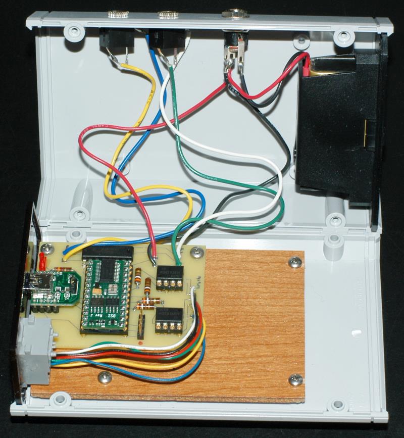
Enclosure:
|

View large picture of the enclosure. Inside of enclosure. |
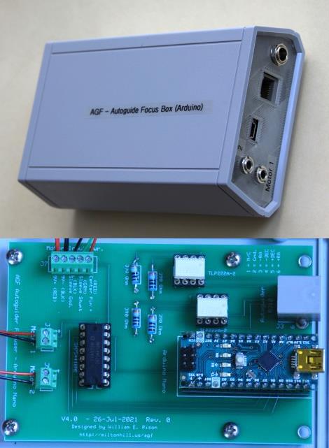
Hardware - AutoGuider Focuser Microprocessor unit (AGFM) using Arduino (2nd Generation Box)
|
||||
|
AutoGuider Focuser Microprocessor unit (AGFM). The AGFM is a microprocessor based control box
that uses the Arduino Nano to control a ST4 type AutoGuider port of any telescope mount. It also
will control 2 DC focus motors using an internal 9VDC battery or 12VDC external power.
|
||||
|
Command protocol:
The AGFM uses commands formated like the ones for an Astro-Physics
GTO controller except for the 2nd focus motor
and initialize command.
The AP GTO only has one focus output and no initialize command.
|
||||
|
|
|
|
|
Command protocol used when connected to Astroberry Raspberry Pi Ekos software:
The following commands are valid after receiving an ACK character or ':U#' command.
ACK sets Meade LX200 mode.:U# sets Astro-Physics mode. The AGFM box with the Arduino can be connected to a Raspberry Pi running the Astroberry software. Kstars and Ekos INDI driver for the Meade LX200 Classic telescope can be selected as the telescope mount and the Focus and manual move controls will work. Only focus motor 1 can be used since the Meade LX200 mount only has one focus function. Addition Meade LX200 commands are programmed into the AGFM box so that no errors are returned when connecting to the AGFM Arduino box. All of these commands are only used to prevent errors when the connecting software thinks the connection is a telescope mount. This allows the AGF box to be used to test some software without having a telescope mount present. |
|
|
|
|
Connecting to PC:
|
|
Found New Hardware:
The first time the AGFM is connected to a PC you may be prompted
to install a new hardware driver. The Arduino uses an FTDI USB to serial chip and Windows install the driver using Connect to Windows Update. |
|
Circuit board layout and parts:
|
|
|
|
|
Schematic, BS2 software and Circuit board:
The board was made by using expresspcb
software and manufacturing.
|

|

|

|

|
|
|
Enclosure:
|
|